本项目是基于机器视觉的植株监护机器人,曾获得2023全国大学生物联网设计竞赛全国二等奖,华东赛区一等奖。
下面是团队分工介绍:
序号
姓名
职务
负责开发板块
1
梁家鸣
算法兼软件开发
ROS通信框架搭建,YOLO视觉定位、SLAM建图和路径规划实现,CV植株图像处理
2
许戈
硬件开发
麦轮底盘的闭环驱动,升降平移台的底层控制,机械臂闭环控制,上下位机通信
3
郭高原
机械设计
设计机器人整体结构及各种连接件的结构
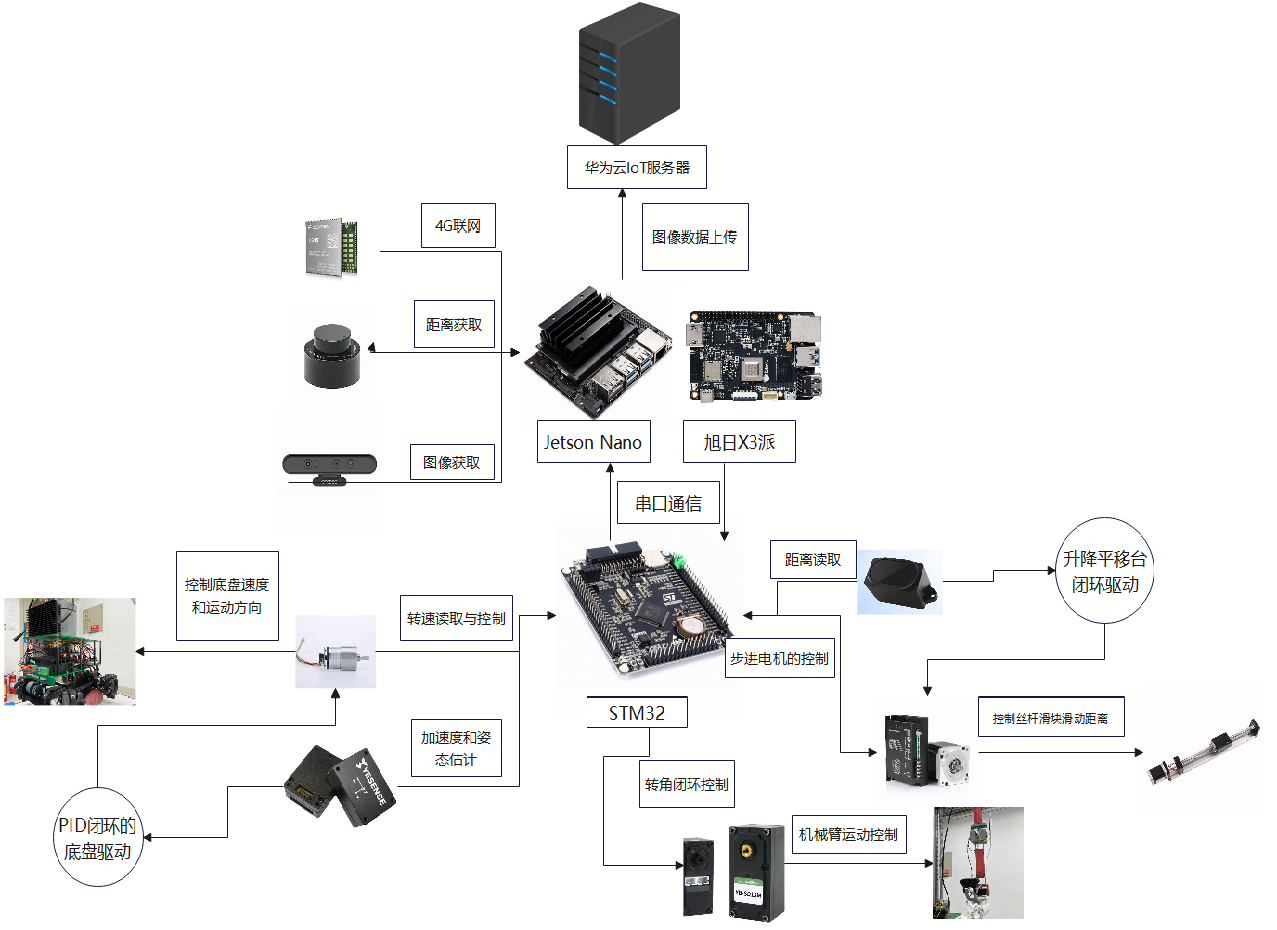
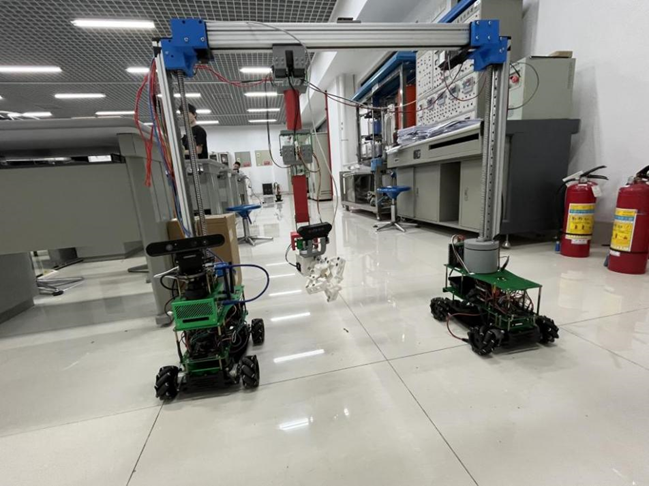
机器人由机械臂运动系统、底盘运动系统、龙门架运动系统组成,由上位机承担视觉感知定位及建图导航任务,传输系统运动控制数据至下位机驱动底盘运动系统到达目标植株附近,在机械臂运动系统及龙门架运动系统的配合下完成植株环绕图像采样任务及植株护理任务。
下面是机器人硬件架构图:
机器人结构
-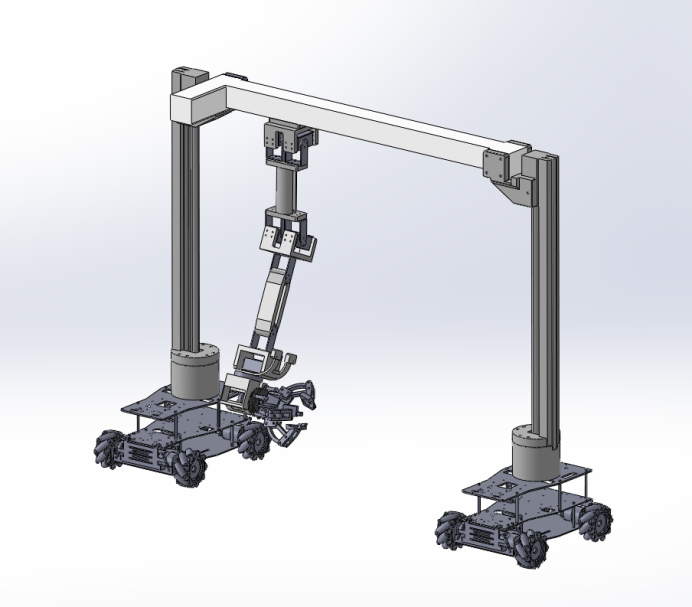
机器人龙门结构:-
该结构有两个丝杆和横杆组成,两个丝杆可以让横杆上下移动,横杆可以让机械臂左右移动,机械臂可由三个自由度,让机械爪灵活到指定位置-
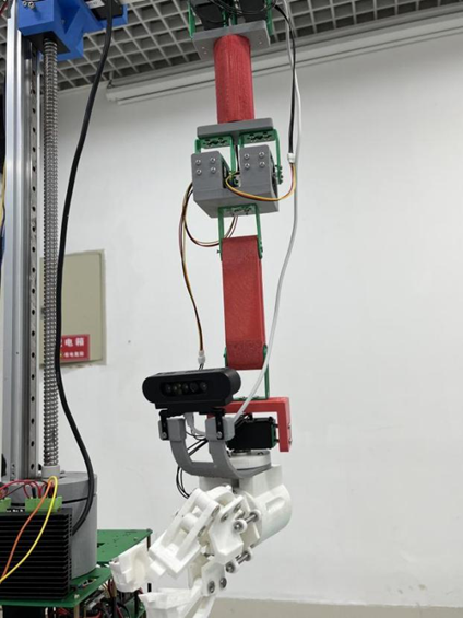
机械臂结构:-
(1)机械臂关节:机械臂关节由六个总线舵机驱动,拥有四个自由度,允许机械臂在不同方向上进行运动。同时总线舵机可以提供精确的角度反馈。-
(2)机械臂手臂:机械臂手臂由PLA材料3D打印而成,用于实际的位移操作。-
(3)机械臂末端夹爪及摄像头:机械臂末端夹爪由PLA材料3D打印而成,负责实际的抓取操作,挂接其上的摄像头负责图像信息的采集。-
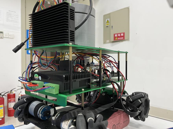
底盘运动系统:-
底盘运动系统由两辆麦克纳姆轮小车组成。-
(1)两辆麦克纳姆轮小车:用于构成底盘运动系统,实现机器人底盘的运动。-
(2)霍尔编码器:安装在直流减速电机上,用于测量电机转速,提供速度反馈信号。
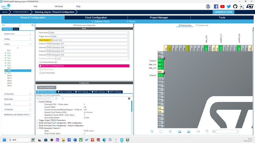
下位机部分
机器人采用STM32F407ZGT6单片机作为下位机,通过总线舵机实现机械臂运动系统每个自由度旋转角度的闭环控制,通过编码器电机实现植株检测机器人底盘运动系统速度的闭环控制,通过激光测距模块实现挂接在龙门架运动系统上的机械臂运动系统水平位置上的闭环控制。
机械臂运动驱动
-
机械臂运动系统是由六个总线舵机、机械外壳组成四自由度机械臂, STM32F407ZGT6通过串口发送转动位置信息给到总线舵机调试板,总线舵机调试板将接收的信息转化为PWM波驱动舵机。舵机高精度电位器作为角度反馈,将线性位置转换为电阻值,并输出精确的电压信号,解算出舵机当前角度通过串口传给STM32F407ZGT6,进而实现机械臂的闭环控制。
void bus_servo_control(uint8_t id, uint16_t value, uint16_t time)
{
    if (value >= 96 && value <= 4000)
    {
        const uint8_t s_id = id & 0xff;
        const uint8_t len = 0x07;
        const uint8_t cmd = 0x03;
        const uint8_t addr = 0x2a;
        const uint8_t pos_H = (value >> 8) & 0xff;
        const uint8_t pos_L = value & 0xff;
        const uint8_t time_H = (time >> 8) & 0xff;
        const uint8_t time_L = time & 0xff;
        const uint8_t checknum =
        (~(s_id + len + cmd + addr + pos_H + pos_L + time_H + time_L)) & 0xff;
        unsigned char data[11] = {0};
        data[0] = 0xff;
        data[1] = 0xff;
        data[2] = s_id;
        data[3] = len;
        data[4] = cmd;
        data[5] = addr;
        data[6] = pos_H;
        data[7] = pos_L;
        data[8] = time_H;
        data[9] = time_L;
        data[10] = checknum;
        Usart_SendStr_length(data, 11);
    }
}
/* 发送读取舵机位置命令 */
void bus_servo_read(uint8_t id)
{
    if (id > 0 && id <= 250)
    {
        const uint8_t s_id = id & 0xff;//只用id
        const uint8_t len = 0x04;
        const uint8_t cmd = 0x02;
        const uint8_t param_H = 0x38;
        const uint8_t param_L = 0x02;

        const uint8_t checknum = (~(s_id + len + cmd + param_H + param_L)) & 0xff;
        // const uint8_t data[] = {0xff, 0xff, s_id, len, cmd, param_H, param_L, checknum};

        unsigned char data[8] = {0};
        data[0] = 0xff;
        data[1] = 0xff;
        data[2] = s_id;
        data[3] = len;
        data[4] = cmd;
        data[5] = param_H;
        data[6] = param_L;
        data[7] = checknum;
        Usart_SendStr_length(data, 8);
    }
}
//转化接收到的值为位置数
uint16_t bus_servo_get_value(void)
{
    uint8_t checknum = (~(Rx_Data[2] + Rx_Data[3] + Rx_Data[4] + Rx_Data[5] + Rx_Data[6])) & 0xff;
    if(checknum == Rx_Data[7])
    {
        // uint8_t s_id = Rx_Data[2];
        uint16_t value_H = 0;
        uint16_t value_L = 0;
        uint16_t value = 0;

        value_H = Rx_Data[5];
        value_L = Rx_Data[6];
        value = (value_H << 8) + value_L;
        return value;
    }
    return 0;
}
底盘运动驱动
底盘运动系统由两辆麦克纳姆轮小车组成,上位机旭日X3派将实时目标速度通过串口通信方式传到下位机STM32F407ZGT6,STM32F407ZGT6通过霍尔编码器解算出的直流减速电机转速,融入PID控制算法输出PWM脉冲,驱动底盘精准运动。-
Encode_motor_now1=__HAL_TIM_GET_COUNTER(&htim5);
__HAL_TIM_GET_COUNTER(&htim5)=0;
//PID控制器
if(Target_speed1>15)Target_speed1=15;
if(Target_speed1<-15)Target_speed1=-15;
error1=Target_speed1-Encode_motor_now1;
pwm_add1=kp*(error1-error_old1)+ki*error1+kd*(error1-2*error_old1+error_last1);
pwm_output1+=pwm_add1;
error_old1=error1;C
error_last1=error_old1;
龙门架运动驱动
龙门架运动系统由两辆麦克纳姆轮小车上方丝杆步进电机及中间的横杆组成,读取IMU惯导模块将角度信息递给STM32F407ZGT6,通过STM32F407ZGT6控制丝杆的升降以适应地形的变化,调平两车中间的横杆。读取激光测距模块的距离数据,驱动横杆上的滑块,使挂接其上的机械臂运动系统实现水平位置上的闭环控制
void Distance_Control(uint16_t TargetDistance,uint16_t CurrentDistance)
{C((TargetDistance-CurrentDistance)>10)
   {
       __HAL_TIM_SetCompare(&htim9, TIM_CHANNEL_1, 500);
       HAL_GPIO_WritePin(GPIOE, GPIO_PIN_4, GPIO_PIN_SET);
   }
   else if((TargetDistance-CurrentDistance)<-10)
   {
       __HAL_TIM_SetCompare(&htim9, TIM_CHANNEL_1, 500);
       HAL_GPIO_WritePin(GPIOE, GPIO_PIN_4, GPIO_PIN_RESET);
   }
   else __HAL_TIM_SetCompare(&htim9, TIM_CHANNEL_1, 0);
//	printf("%lf\r\n",TargetDistance-CurrentDistance);
}
//面向十轴IMU模块的时候,向右倾斜角度为正,向左倾斜角度为负
//对于丝杆RESET是上升,SET是下降
void Horizontal_bar_leveling(float Angle)
{
   if(Angle>3)
   {
       HAL_GPIO_WritePin(GPIOC, GPIO_PIN_13, GPIO_PIN_RESET);
       __HAL_TIM_SetCompare(&htim9, TIM_CHANNEL_1, 500);
   }
   else if(Angle<3)
   {
       HAL_GPIO_WritePin(GPIOC, GPIO_PIN_13, GPIO_PIN_SET);
       __HAL_TIM_SetCompare(&htim9, TIM_CHANNEL_1, 500);
   }
   else __HAL_TIM_SetCompare(&htim9, TIM_CHANNEL_1, 0);
}
上位机部分
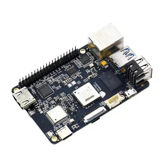
上位机部分主要由旭日X3派完成植株图像处理部分,旭日X3派具有5Tops端侧推理与4核ARM A53处理能力,依赖于旭日X3派BPU高性能计算架构,预训练的目标检测模型得以在板端进行高效推理。旭日X3派支持同时多路Camera Sensor的输入并支持H.264/H.265编解码,能更高效完成图像采集处理任务,为后期的植株三维点云建模打下基础。我们在X3派上完成下面的植株图像采样任务
import cv2
import time

sampling_interval = 1

cap = cv2.VideoCapture(0)

if not cap.isOpened():
    print("无法打开摄像头")
    exit()

fps = cap.get(cv2.CAP_PROP_FPS)

last_sample_time = time.time()

while True:
    ret, frame = cap.read()
    if not ret:
        print("无法读取帧")
        break

    filtered_frame = cv2.blur(frame, (3, 3))
    cv2.imshow("Filtered Frame", filtered_frame)

    current_time = time.time()

    if current_time - last_sample_time >= sampling_interval:
        cv2.imwrite(f"sample_{current_time}.jpg", filtered_frame)
        print("采样图像已保存")

        last_sample_time = current_time

    if cv2.waitKey(1) & 0xFF == ord('q'):
        break

cap.release()
cv2.destroyAllWindows()
视觉定位模块
视觉定位模块主要结合yolo目标检测算法和ROS通信框架,让机器人能通过视觉感知到植株,并解算出植株的方位,将其输出为目标点输入到建图导航的规划框架中
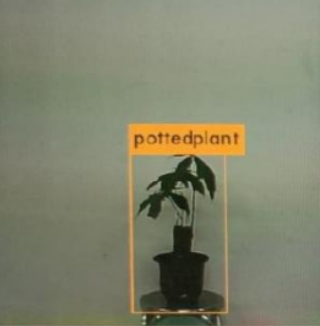
darknet_ros软件包将ROS和YOLO很好的融合在一起,为机器人视觉任务开发提供了更多可能性。目标的深度测距的实现我们可以结合darknet_ros功能包,我这里用的是RGBD相机,型号是Astra_Pro,深度相机节点在启动后会输出深度图的话题
rostopic list

/camera/depth/image_rect_raw
查看一下darknet_ros功能包的msg消息文件,下面是BoundingBoxes.msg消息文件
Header header
Header image_header
BoundingBox[] bounding_boxes
下面是BoundingBox.msg消息文件
float64 probability
int64 xmin
int64 ymin
int64 xmax
int64 ymax
int16 id
string Class
用rostopic info命令可以看到/darknet_ros/bounding_boxes话题的具体内容
rostopic info /darknet_ros/bounding_boxes

Type: darknet_ros_msgs/BoundingBoxes

Publishers:
 * /darknet_ros (http://localhost:43545/)
这个话题就是我们需要的目标检测框的信息,将目标检测框输出到深度图我们就可以读取目标的深度。首先创建一个scripts文件夹,创建ObjectLocation.py文件,目标深度测距的代码思路首先导入rospy、cv2、numpy、darknet_ros_msgs等包,创建一个目标定位的类,实例化类的一些参数,订阅深度图话题并转化为深度矩阵,订阅目标检测框将坐标信息对齐到深度图中,按照3x3滑动窗口遍历检测框进行中值滤波,最后取中心深度作为目标的估计深度,并发布距离话题
#!/usr/bin/env python
#-*- coding: utf-8 -*-
import rospy
import cv2
from cv_bridge import CvBridge, CvBridgeError
from sensor_msgs.msg import Image
from darknet_ros_msgs.msg import BoundingBoxes
import numpy as np
from scipy.ndimage import median_filter
import math


class ObjectLocation:

    def __init__(self):
        self.bridge = CvBridge()
        self.depth_image = None
        self.bounding_boxes = None
        self.probability = 0
        self.Class = None
        self.distance = 0
        self.centerx = 0
        self.centery = 0
        self.x_h = 0
        self.y_h = 0
        self.w_h = 0
        cv2.destroyAllWindows()

    '''
    get depth distance from found object rect
    '''
    def depthDistanceFromCoordinate(self, data):
        try:
            self.depth_image = self.bridge.imgmsg_to_cv2(data, "passthrough")
            depth_array = np.array(self.depth_image, dtype=np.float32)
            filter_depth_array = np.zeros_like(depth_array)
            if self.bounding_boxes != None:
                for bounding_box in self.bounding_boxes:
                    # bounding box coordinates
                    # less than 0 and larger than width or height
                    xmin = 0 if bounding_box.xmin < 0 else bounding_box.xmin
                    xmax = bounding_box.xmax if bounding_box.xmax < len(depth_array[0]) else len(depth_array[0])
                    ymin = 0 if bounding_box.ymin < 0 else bounding_box.ymin
                    ymax = bounding_box.ymax if bounding_box.ymax < len(depth_array) else len(depth_array)
                    dep_aver = 0
                    filter_depth_array = median_filter(depth_array, size=(3, 3))
                    dep_aver = filter_depth_array[int((ymin + ymax) / 2), int((xmin + xmax) / 2)]
                    self.probability = bounding_box.probability
                    self.Class = bounding_box.Class
                    self.distance = dep_aver
                    self.centerx =  (xmin + xmax) / 2
                    self.centery =  (ymin + ymax) / 2
                    rospy.loginfo("Class=%s, Probability=%f, Distance=%f", self.Class, self.probability, self.distance)
                    pub = rospy.Publisher('/darknet_ros/distance', self.distance, queue_size = 100)
                    pub.publish(self.distance)
        except Exception as e:
                print(e)


    def bbox_callback(self, msg):
        self.bounding_boxes = msg.bounding_boxes


if __name__ == '__main__':
    od = ObjectLocation()
    rospy.init_node('ObjectLocation', anonymous=True)
    rospy.Subscriber('/darknet_ros/bounding_boxes', BoundingBoxes, od.bbox_callback)
    rospy.Subscriber('/camera/depth/image_rect_raw', Image, od.depthDistanceFromCoordinate)
    rate = rospy.Rate(10)
    rate.sleep()
    rospy.spin()
我们需要根据相机内外参去解算目标的方位,相机内参外参原理参照下面链接,依据成像原理我们可以将在像素坐标系下的目标映射到相机坐标系,运行标定相机的demo就可以得到相机的内参外参矩阵,我的是出厂就标定好的附带内参矩阵,内参矩阵是相机出厂时就决定了的
image_width: 640
image_height: 480
camera_name: camera
camera_matrix:
  rows: 3
  cols: 3
  data: [ 581.88585,    0.     ,  314.2472 ,
            0.     ,  592.27138,  210.27091,
            0.     ,    0.     ,    1.     ]
camera_model: plumb_bob
distortion_model: plumb_bob
distortion_coefficients:
  rows: 1
  cols: 5
  data: [0.221666, -0.575455, -0.014215, 0.003895, 0.000000]
rectification_matrix:
  rows: 3
  cols: 3
  data: [ 1.,  0.,  0.,
          0.,  1.,  0.,
          0.,  0.,  1.]
projection_matrix:
  rows: 3
  cols: 4
  data: [ 591.88599,    0.     ,  315.96148,    0.     ,
            0.     ,  603.39893,  205.72873,    0.     ,
            0.     ,    0.     ,    1.     ,    0.     ]
相机的外参矩阵则要确定机器人坐标系下的相机位姿,才能将目标方位解算到机器人bse_link坐标系下。用Python程序设定导航目标点的主要通过ROS中名为"move_base"的动作服务器(Action Server),负责接收和处理导航目标,我们将导航目标点位姿信息解算好,发送到move_base节点即可。
在原有的ObjectLocation.py上导入actionlib、tf、move_base_msgs等包,使用矩阵求逆加内积来将像素坐标系下的目标位置映射到相机坐标系,再通过tf坐标变换映射到机器人坐标系,实例化导航目标点,将目标点位姿发送到move_base节点,等待动作服务器响应即可
#!/usr/bin/env python
#-*- coding: utf-8 -*-
import rospy
import cv2
from cv_bridge import CvBridge, CvBridgeError
from sensor_msgs.msg import Image
from darknet_ros_msgs.msg import  BoundingBoxes
import numpy as np
from scipy.ndimage import median_filter
import actionlib
from move_base_msgs.msg import MoveBaseAction, MoveBaseGoal
import tf.transformations as tr
import math


class ObjectLocation:

    def __init__(self):
        self.bridge = CvBridge()
        self.depth_image = None
        self.bounding_boxes = None
        self.probability = 0
        self.Class = None
        self.distance = 0
        self.centerx = 0
        self.centery = 0
        self.x_h = 0
        self.y_h = 0
        self.w_h = 0
        cv2.destroyAllWindows()

    '''
    get depth distance from found object rect
    '''
    def depthDistanceFromCoordinate(self, data):
        try:
            self.depth_image = self.bridge.imgmsg_to_cv2(data, "passthrough")
            depth_array = np.array(self.depth_image, dtype=np.float32)
            filter_depth_array = np.zeros_like(depth_array)
            if self.bounding_boxes != None:
                for bounding_box in self.bounding_boxes:
                    # bounding box coordinates
                    # less than 0 and larger than width or height
                    xmin = 0 if bounding_box.xmin < 0 else bounding_box.xmin
                    xmax = bounding_box.xmax if bounding_box.xmax < len(depth_array[0]) else len(depth_array[0])
                    ymin = 0 if bounding_box.ymin < 0 else bounding_box.ymin
                    ymax = bounding_box.ymax if bounding_box.ymax < len(depth_array) else len(depth_array)
                    dep_aver = 0
                    filter_depth_array = median_filter(depth_array, size=(3, 3))
                    dep_aver = filter_depth_array[int((ymin + ymax) / 2), int((xmin + xmax) / 2)]
                    self.probability = bounding_box.probability
                    self.Class = bounding_box.Class
                    self.distance = dep_aver
                    self.centerx =  (xmin + xmax) / 2
                    self.centery =  (ymin + ymax) / 2
                    rospy.loginfo("Class=%s, Probability=%f, Distance=%f", self.Class, self.probability, self.distance)
                    if self.Class == "pottedplant":
                        fx = 581.88585
                        fy = 592.27138
                        cx = 314.2472
                        cy = 210.27091
                        K = np.array([[fx, 0., cx], [0., fy, cy], [0., 0., 1.]])
                        point_pixel = np.array([self.centerx, self.centery, 1])
                        point_camera = np.dot(np.linalg.inv(K), point_pixel) * self.distance
                        self.y_h = - point_camera[0] - 460
                        self.x_h = point_camera[2] + 110
                        orientation = tr.quaternion_from_euler(0, 0, math.atan2(self.y_h, self.x_h))
                        self.w_h = orientation[3]
                        rospy.loginfo("%s Goal location is x_h = %f, y_h = %f, w_h=%f", "pottedplant", self.x_h, self.y_h, self.w_h)
                        self.movebase_callback()
                    pub = rospy.Publisher('/darknet_ros/distance', self.distance, queue_size = 100)
                    pub.publish(self.distance)
        except Exception as e:
                print(e)


    def movebase_callback(self):
        try:
            client = actionlib.SimpleActionClient('move_base', MoveBaseAction)
            client.wait_for_server()
            goal = MoveBaseGoal()
            goal.target_pose.header.frame_id = "base_link"
            goal.target_pose.pose.position.x = self.x_h * 4 / 5000
            goal.target_pose.pose.position.y = self.y_h * 4 / 5000
            goal.target_pose.pose.orientation.w = self.w_h
            client.send_goal(goal)
            rospy.loginfo("move_base set goal success!")
            client.wait_for_result()
        except Exception as e:
            print("movebase_callback service failed")

    def bbox_callback(self, msg):
        self.bounding_boxes = msg.bounding_boxes


if __name__ == '__main__':
    od = ObjectLocation()
    rospy.init_node('ObjectLocation', anonymous=True)
    rospy.Subscriber('/darknet_ros/bounding_boxes', BoundingBoxes, od.bbox_callback)
    rospy.Subscriber('/camera/depth/image_rect_raw', Image, od.depthDistanceFromCoordinate)
    rate = rospy.Rate(10)
    rate.sleep()
    rospy.spin()
其实还可以用其他滤波方法让深度估计更加精确,用重采样方法让方位估计更加精准
SLAM建图与路径规划
SLAM建图采用Gmapping算法,GMapping算法是经典的激光SLAM算法,在移动机器人建图中被广泛使用,它使用粒子滤波器来估计移动机器人在环境中的位置,并同时构建环境的地图。-
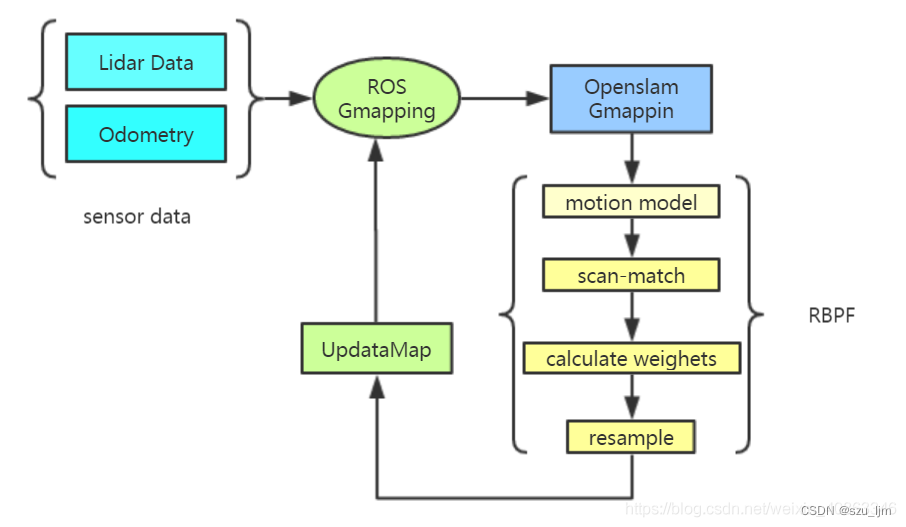
粒子滤波器是一种基于蒙特卡罗方法的概率滤波器,用于估计随时间变化的状态量。它通过在状态空间中随机采样一组粒子来表示当前状态的不确定性,并通过对这些粒子进行加权来计算状态的后验概率分布。在机器人定位和建图问题中,粒子滤波器通常用于估计机器人在环境中的位姿和地图的特征。
Gmapping算法集成了AMCL定位算法,AMCL(自适应蒙特卡洛定位)是一种基于粒子滤波器的机器人定位方法,其主要目标是根据机器人的传感器数据来估计其在环境中的位姿。
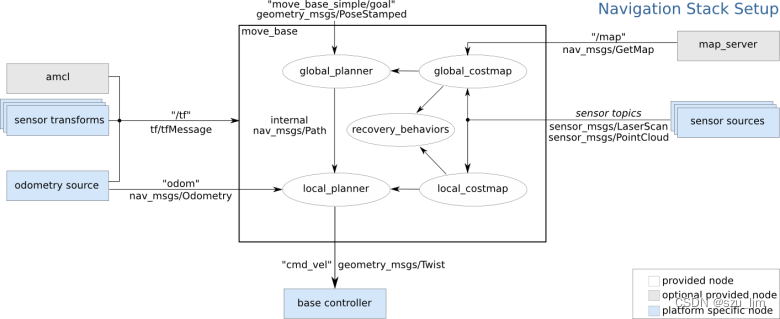
路径规划采用move_base框架, 融合A*全局规划算法和DWA局部规划算法。move_base是一个用于移动底盘的功能包,提供了一种方式让机器人在地图中安全地导航到目标位置。move_base 将全局路径规划器和局部路径规划器结合起来,形成一个完整的导航框架。
<launch>
    <!-- 设置地图的配置文件 -->
    <arg name="map" default="nav.yaml" />
    <!-- 运行地图服务器,并且加载设置的地图-->
    <node name="map_server" pkg="map_server" type="map_server" args="$(find mycar_nav)/map/$(arg map)"/>
    <!-- 启动AMCL节点 -->
    <include file="$(find mycar_nav)/launch/amcl.launch" />

    <!-- 运行move_base节点 -->
    <include file="$(find mycar_nav)/launch/path.launch" />
    <!-- 运行rviz -->
    <node pkg="rviz" type="rviz" name="rviz" />

</launch>
总结
植株监护机器人整体开发框架比较庞大,目前仍有一些模块还在开发中,无论是机械、电控、规划、感知,都需要紧密协同才能让机器人有更高的主动性。我们希望借助地平线机器人的开发平台,让更多志同道合的开发者一起完善项目,一起乐享开发!